Trimble has released new version of its CAD software Trimble Business Center v 5.50. At first glance there are lots of improvements. To see the full list check out the release notes or read on. Will post all of them in this article
How to upgrade to Trimble Business Center v5.50?
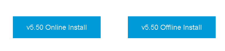
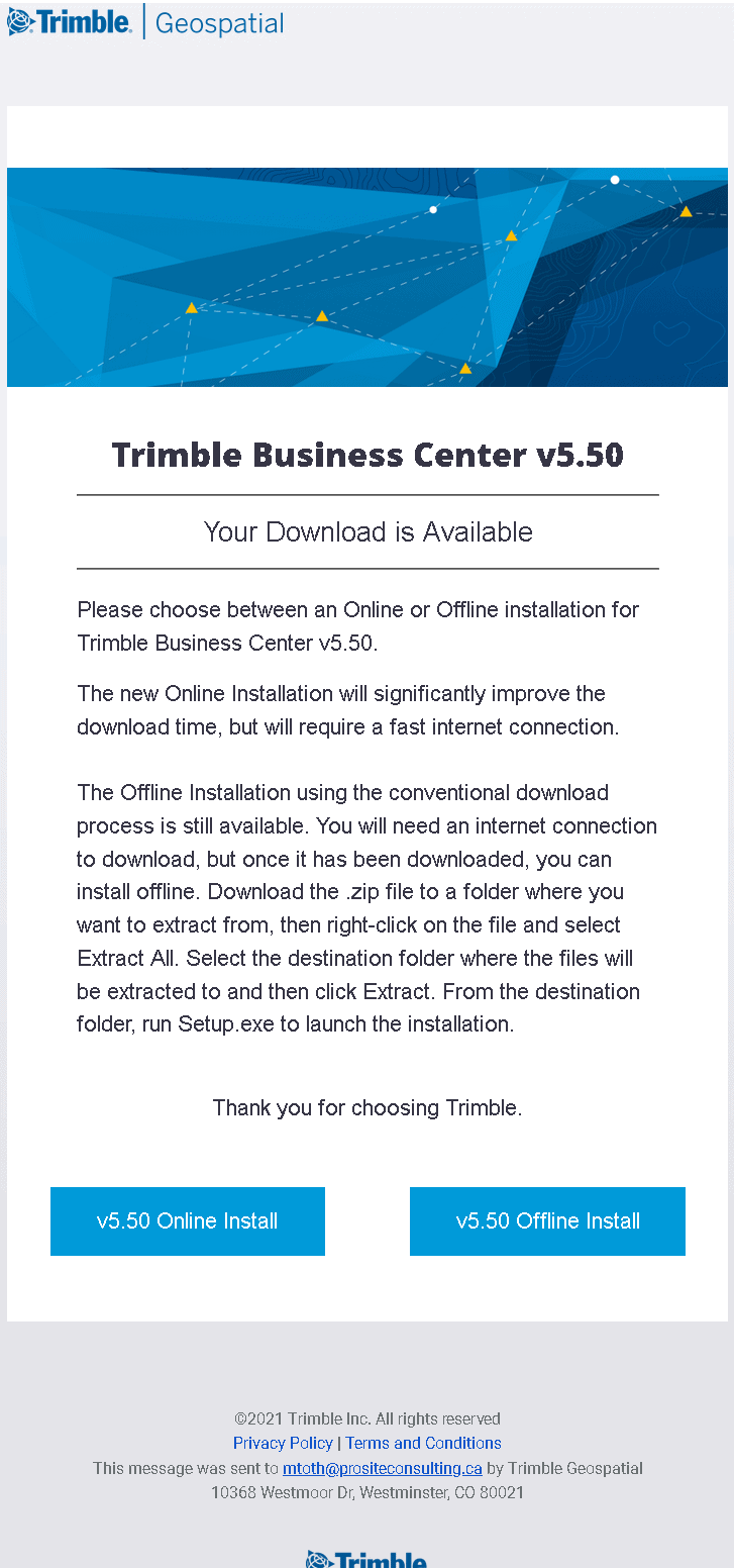
To upgrade to Trimble Business Center v5.50 you will need a current active Trimble Business Center subscription. When you open your current version of Trimble Business Center and click update under your Support tab. When you click on the upgrade you will be directed to the Trimble web where after entering your credentials you will be redirected to a page which will send you an email with instructions on how to download the new version of Trimble Business Center. This time there re two option online and offline.
What are the highlighted new features in Trimble Business Center v5.50?
- Updated ArcGIS connection to ArcMap and ArcPro
- Enhanced IFC and TRB support
- Numerous Aerial Photogrammetry workflow improvements
- Added capabilities and semi-automated approaches for linear feature extraction and extracting cross-sections from point clouds
- Improved Tunneling and Monitoring inspection workflows for analysis and reporting
- New entry-level TBC Starter subscription edition to better align with customer needs
How long does it take to get the email with download link to Trimble Business Center v5.50?
It was pretty much instant. The minute I have hit register email showed up with instructions. Here is a screen shoot of the email itself. Looks like lots of new features and upgrades went into the whole process. No more just a simple link.
What is the complete list of new features?
Here is the copy and paste list from the release notes:
Survey
- Import as-staked polyline points from Trimble Access – In support of the polyline stakeout feature in Trimble Access, TBC now allows you to import from the field software as-staked points for polyline geometry, enabling you to check deltas compared to design polylines. This is in addition to the existing support for the following types of as-staked points: normal points, line points, alignment points, surface points, corridor points, and catch points.
- Spectra Geospatial Origin field software support – TBC fully supports the import and export of survey data collected using Spectra Geospatial’s newest field software: Origin. Origin is a full-featured, Android and Windows-supporting, modern software built to meet the needs of survey professionals, and it is intended as an upgrade/replacement for Spectra Geospatial Survey Pro.
- Share time-dependent transformation parameters with Trimble Access – The JXL importer and exporter in TBC have been updated to include time-dependent transformation data to ensure transformation is performed using the same parameters in both TBC and Trimble Access, regardless of the version of the Coordinate System Database being used with each.
- Global reference datum and epoch for a datum transformation – The Coordinate System Manager has been enhanced to display the global reference datum and epoch used as the origin for a datum transformation. When creating a custom datum, you will be able to select the global datum and epoch in the list of reference datum supported by the Trimble Geodetic Library. In TBC, the datum and epoch selected for the current coordinate system are displayed in the Coordinate System group in Project Settings.
- Updates to Coordinate System and Time-Dependent Transformation databases –
The newest Coordinate System Database installed with TBC includes the following enhancements:
- Updated geoid model for Guyane.
- Added legacy geoid models HT2_1997, HT2_2002v70 and HT2_2010v70 for Canada.
- Fixed Hungarian geoid Vitel14.
- Added Nova Scotia zones 4 & 5 for Canada (Atlantic).
- Added new geoid RAF18v2 for France.
- Added datum and zone PSD93 / UTM N057E used in Oman.
- Added new zones and geoid model for Senegal.
- Added new geoid model 2020 for Lithuania
- Fixed WKT parsing of EPSG:28992. “RD_New” should resolve to zone 4800 = “RD 2018”.
- Added new zone CABA 2019 for Buenos Aires, Argentina.
- Updated ITRF realizations to ensure they are used at epoch of measurement.
- Improved RTX in Belgium using correct global reference datum.
- Improved RTX in Switzerland using correct global reference datum.
- Improved RTX in Poland using correct global reference datum.
The newest Time-Dependent Transformation Database installed with TBC, which is used to transform between ITRF 2014 at the epoch of measurement and the global reference frame, includes the following enhancements:
- Checked and updated <DataSource> for time-dependent transformation parameters.
- Added support for SnakeGrid for V4 file and ASA parameters.
- Added grid transformations from GDA2020 to GDA94.
- Added displacement model for KGD2002 in Korea.
- Added displacement model for JGD2011 in Japan.
- Improved local displacement model for New Zealand.
- Added support for new datum RGF93v2b in France.
- Renamed ETRF2000(R05) to ETRF2000.
- Added transformations parameters between ITRF2014 and NAD83(2011/MA11/PA11).
- Added support for datum LKS-92 used in Latvia.
- Added support for EUREF-NKG-2003 used in Lithuania.
- Added support for ETRF2000 (EPOCH:2010.5 and 2017.5) used in the Netherlands.
- Added support for CA SRS epoch 2017.50 (NAD83) used in California.
- Added support for KSA-GRF17 used in Saudi Arabia.
- Fixed SIRGAS-CON and SIRGAS1995, which were not working.
- Added ETRS89-DREF91 at epoch 2000 for legacy software.
- Fixed Canadian displacement model CSRS Velocity Grid V7.0 to be usable at any epoch.
- Improved transformation between ITRF2014 and ITRF1988.
- Improved transformation between ITRF2014 and ETRS89.
- Enhanced Trimble Sync – The Trimble Sync command, which allows you to share and synchronize data between TBC and Trimble Access via Trimble Sync Manager and Trimble Connect, has been enhanced to enable the sharing of the following types of data:
- Text – Save selected text objects, along with their specified size and style, to a DXF file to be shared with Trimble Access, where they are displayed in the same size, style, and location as was specified in TBC.
- Corridor surfaces – Save selected corridor surfaces, along with their associated corridor alignment data, to a LandXML file to be shared with Trimble Access.
- Tunnel designs – Save selected tunnel designs, along with their associated tunnel alignment data, to a TXL tunnel file to be shared with Trimble Access.
This is in addition to the already supported sharing of point and linework data.
- Disable redundant backsight observations from Trimble Access – After importing Trimble Access MTA data that includes disabled foresight observations, the associated redundant backsights, which are imported as enabled, are included in the Import Summary Report and the Flags pane alerting you to the fact that you may want to disable them, which you can do easily and efficiently with one click of the new Disable Redundant Backsights command. When a redundant backsight is disabled, the corresponding station point is updated accordingly when you recompute the project.
GIS
- New ArcGIS connection component – ArcGIS users can use the GIS Connection Manager command to connect to a file geodatabase, and enterprise geodatabase to download schemas and upload features using the new and updated ArcGIS provider.
CAD
- Include interior regions in tracked outlines – Use the Merge Holes to Boundary option to include inside linework (e.g., islands) in resulting geometry when using the Track Region Outline command.
- Create and edit dependent points – Create CAD points with coordinates derived from dependencies on other objects. A dependent point can be based on a station, percentage along a line, intersection, or another point. If any of the source geometry changes, the dependent point is updated accordingly. Similarly, if you create lines that rely on a dependent point, those lines will update any time one of the points is changed.
- Enhanced IFC support – IFC (Industry Foundation Classes) is a commonly used schema for Building Information Modeling (BIM) data. The hierarchy of the schema used to define an IFC 3D model can include a large number of objects, each representing a physical architectural component. IFC support in TBC has been enhanced as follows.
- Import and export Trimble TrimBim (TRB/.trb) files containing BIM/IFC data that can display varying types of geometry in the graphic views, including meshes and linework.
- View the IFC hierarchy of BIM objects nested beneath the BIM Data parent node in the Project Explorer. And, view read-only BIM entity properties.
- Export all or some of the BIM entities in your project in a single TRB (.trb) file. (This allows you to export entities from multiple IFC projects that have been imported into your TBC project in a single export file.)
- Import lines, polylines, and arcs from Trimble Access – In support of the line creation features in Trimble Access, TBC now allows you to import lines, polylines, and arcs that were drawn (keyed in) in Trimble Access and are contained in a JobXML file (.jxl) as editable linestrings displayed in graphic views in your TBC project.
- Layer Group and Selection Set added to Properties pane – The Properties pane for common CAD objects (for example, points, lines, text, blocks, and dimensions) has been enhanced as follows:
- A Layer Group field has been added that allows you to view or change the layer group to which an object’s layer is assigned. (This field displays only if you have defined layer groups in your project.)
- A Selection Set field has been added that allows you to view, change, or create a selection set to which an object is assigned (previously available only in points Properties).
- Easily select groups of associated objects – When selecting objects in a graphic view, you can now press the Ctrl key when you make your first object pick and all of the objects contained in the same group as the picked object (for example, sheets, labels, side slopes, and so on) will be selected.
- Multiple grip selection option – The Display pane in the Options dialog now includes an option to display grips for a selected CAD line segment and for a specified number of adjacent line segments, enabling you to display just the number of grips with which you want to work. This ensures you are in control of how many grips are displayed when you select a segment.
- CAD Leader lines – If a CAD leader line is not associated with a text label (for example, the associated label text was exploded), you can associate it with any text label using the new “Source text” field in the CAD Leader Properties pane.
Surfaces
- Create a surface offset from another surface – Create a new surface based on an offset from another surface. This command simply makes a copy of an existing surface and shifts it up or down on the Z-axis. You can also leave the delta elevation at 0.00 to make a copy of the surface in place, such as for historical topography comparisons over time.
- Combine multiple surfaces – Make a single surface from two or more separate, non- contiguous surfaces that do not overlap. In the new combined surface, no triangles are formed between the separate parts (the previously independent surfaces).
- Explode a surface – Break a surface into its component linestrings and CAD points. The linestrings are attached to the CAD points by reference, so if you move one of the points, all the lines connected to it will move. If desired, you can also choose to explode a surface just where the slope changes beyond a specified vertical angle tolerance.
- 3D Drive View enhancements – The 3D Drive View has been enhanced as follows:
- Drive across one of two selected surfaces to identify cuts and fills. For example, you can drive across a final graded surface to identify cuts and fills related to the initial ungraded surface at precise coordinates.
- If you change the zoom level or view direction while driving along an alignment or across a surface, click the new Reset button at any time to reset the default zoom level and default straight-ahead view.
- Use the Project Settings to select from a predefined list of vehicle, instrument, and people icons (Sketchup models) to display in the view, or create your own and easily import it into your project.
- As an alternative to the first-person from-vehicle view, use the Project Settings to select a third-person view from behind the vehicle at varying distances and heights as necessary to optimized the perspective.
- Select a line or alignment along which the vehicle will self-drive.
- Use your Arrow keys to conveniently turn the vehicle when driving across a surface.
Corridors
- Apply advanced tilt properties to roundabouts – Use these two new roundabout tilt methods for intersection and cul-de-sac roundabouts:
- Automatic tilt all circles – The outer circle defines the circular plane by finding the roundabouts intersection points with leg alignments; this sets the tilting values of slope and direction. The inner circle and inner shoulder are parallel with the plane defined by the outer circle. You also can specify these properties for offsetting two inner lines: Vertical offset inner shoulder and Vertical offset inner circle. These properties are used to move both of these inner lines up/down.
- User-defined tilt all circles – Specify the tilt (slope and direction) of both the inner and outer circles manually. Optionally, you can specify the vertical offset between the inner and outer circles. The lane and inner shoulder slopes are calculated automatically.
- Enhanced corridor export options – The export options available on the Corridor tab in the Export command have been enhanced with name changes that are more descriptive of the individual exporters, making choosing the right corridor exporter easier and more intuitive.
Point clouds
- Extract cross-sections from a point cloud – Use the new Extract Cross-Sections from a Point Cloud command to extract open or closed 3D cross-section line segments from a point cloud based on any of the following:
- Two scan points – Select start and end scan points to create a line and extract a single cross-section along the line (for example, creating a contour line along a stockpile).
- Reference lines – Select one or more linear objects (such as linestrings or CAD lines) to extract one or more cross-sections along the lines (for example, extracting underground mine profiles along predefined drilling/excavation reference lines).
- An alignment – Select an alignment or other linear object (such as a linestring) and specify the intervals and offsets to use to extract one or more cross-sections perpendicular to the alignment or line (for example, extracting cross-sections along an alignment of a scanned roadway).
- Define complex profiles for curb and gutter line extraction – The Extract Line Feature command, which allows you to create linestrings from curb and gutter features displayed in a point cloud, has been enhanced to allow you to select up to ten nodes (four was the previous limit) to define more complex feature profiles for line extraction, such as road barriers, and curb and gutter with sidewalks.
- Auto-select overhead utility lines for line extraction – The Extract Line Feature command, which allows you to create linestrings from overhead utility line features displayed in a point cloud, has been enhanced to auto-select lines that are parallel and adjacent to a selected line within the distance you specify. This can be very helpful if you are extracting many lines as might be the case, for example, with large power towers.
- Export Trimble X7 data to Trimble TMX – Use the new X7 to TMX exporter to export Trimble X7 laser scanner data to the Trimble TMX-2050 Display System, which features a large high-definition touch screen with sharp visuals and a choice of FmX® Plus or Precision-IQ™ display applications to suit your specific farm practices.
Construction data
- Remove dependent data from field-bound VCL designs – When exchanging data between TBC projects using VCL export/import, ‘intelligent’ dependencies (and the dependent objects) are retained. This can lead to unnecessary data and larger file sizes on field devices. Therefore, now when sending data from TBC to field systems (Siteworks and Earthworks) as designs via WorksManager, dependent objects for surfaces and road surfaces (e.g., the points and lines that define them) are not included. Typically, those objects are not needed for field work and eliminating them makes VCL files much smaller and more usable by the field devices and machine controllers.
This behavior is controlled by the Cleanup VCL file property in TBC. By default, this property is set to Yes for WorksManager projects.
Photogrammetry
- Support for GNSS quality data from DJI aerial photo stations – If RTK is used when recording DJI aerial photo images, TBC extracts the RTK quality information from the imported metadata for each image, enabling an absolute orientation adjustment to be performed without the need to process baselines or measure ground control points. Although the use of GCPs and baseline processing are still recommended if adequate data is provided, this enhancement is very useful in cases where no GCPs are provided and either no T02 file was included or the Internet Download for the region or time frame does not offer data to run baseline processing.
- Aerial photo processing enhancement – Aerial photo processing in TBC has been enhanced to provide faster adjustment and processing with more accurate results, and provide wider support for the various UAS/UAV products available.
- DJI Phantom 4 UAV support – TBC now supports the import and processing of aerial photo data collected with a non-RTK DJI Phantom 4 UAV equipped with a 20MP model FC6310 camera, as is included with the Phantom 4 Pro and Phantom 4 Advanced.
- DJI Zenmuse P1 UAV support – Use the Import DJI UAV Data command to import aerial survey data collected by the new DJI Zenmuse P1 UAV. Then, use a GCP-based workflow (GNSS post-processing is not yet supported) to adjust the data and create deliverables (point clouds, elevation rasters, and/or orthomosaics) in TBC, or pass the data through to UASMaster for processing. Designed for photogrammetry flight missions, the Zenmuse P1 integrates a full-frame sensor with interchangeable fixed- focus lenses on a 3-axis stabilized gimbal.
- ECW compressed aerial images support – You can now import georeferenced ECW (Enhanced Compression Wavelet) aerial image files with embedded map projection information to use as background images in TBC. ECW technology provides exceptional compression, capable of reducing very large files to five percent of their original size, while retaining the image’s full visual quality. Because of the small file size provided by the ECW format, files can easily be stored, transferred, and displayed, even on small devices. ECW-formatted images are supported in all TBC graphic views, including dynaviews and plotboxes, and can be used as a background map. Use the Options command to specify whether to copy ECW files into the project folder on import, or reference them at their current location.
- Create orthomosaic with transparent background – The Create Orthomosaic command, which is used to create an orthomosaic photo image from imported aerial survey data that can be exported to other software packages for display or additional processing, now provides an option to specify that orthomosaic background pixels (pixels not covered by any of the ortho images) be rendered transparent.
- Radiometric corrections applied to aerial photo images – TBC applies radiometric corrections to aerial photo images automatically during the photo station adjustment process to improve the interpretability and quality of the images. The corrections compensate for over- or under-lit areas within images (due to image exposure, focal length, the sun’s azimuth/elevation, and atmospheric conditions), resulting in images that are more evenly lit, and in which fine detail is more easily discernible. The radiometric corrections, which are applied very quickly during the adjustment process (minimal impact on processing time), are contained in small RDX (.rdx) files stored in your project folder (one for each photo image).
Tunnels
- Monitor tunnel convergence points – Use the new Assign Tunnel Convergence Points command along with the Trimble Monitoring Cloud service to monitor tunnel convergence points by storing and comparing coordinates for tunnel points that have been measured in the field on multiple occasions over a period of time and imported into TBC where they are processed and adjusted as necessary. The cumulative data tracks movement over time resulting from tunnel deformation, which can be viewed in graphic and tabular views using the Convergence Points tab in the Tunnel View or in the customizable Tunnel Convergence Report. Displacements generated by this analysis are reported relative to the tunnel design alignment in terms of station, offset, and elevation.
- Specify label interval in Tunnel Inspection Cross-Section View – Use Project Settings to specify the distance interval at which labels are displayed in the Tunnel Inspection Cross-Section View. This setting is useful when you want to maintain a high level of density in the Inspection Plan View while still being able to view readable labels in the Cross-Section View.
- View as-built points in the Tunnel View – Use the Tunnel View command to quickly view a graphical and tabular comparison between assigned as-built points and a tunnel design to determine overbreak and underbreak information for construction verification and quality control, similar to the information displayed in the Tunnel As-Built Report.
Monitoring
- Point monitoring enhancements – The point monitoring feature in TBC has been enhanced as follows:
- After selecting points to monitor, the automatic synchronization process begins immediately (no need to first run the Sync Monitoring command as before). This eliminates the need for an additional command when adding new epochs to a monitoring project.
- You can select any monitoring point in the Project Explorer and select to delete it from the current epoch or from all epochs. This provides additional flexibility for managing monitoring projects in TBC.
Mobile Mapping
- Enhancement of the Target Picker in the Intersected Plane – You can define a rectangular pattern by picking three consecutive and connected vertices.
Data prep
- Apply a Virtual Break rule to a line in a vertical design – Use the Virtual Break rule to split a line into sections without actually breaking it (such as would be done by the Break Line command). The Virtual Break rule helps you work more efficiently when have to edit short sections of a long line. Sometimes a line must be divided into pieces to isolate the area that will be computed, without needing to actually break the line into smaller lines.
Support
- Licensing updates – To better align features with targeted workflows and customer needs, the following licensing changes have been made for this release of TBC:
- A new entry-level TBC Starter subscription edition has been added for GNSS, total station, and digital level-based workflows as well as basic machine and field data file preparations.
- The Sample Point Cloud Region and Sample Region by Intensity commands are now included with the Surface Modeling Edition perpetual license and available in all subscription license editions except the new entry-level TBC Starter.
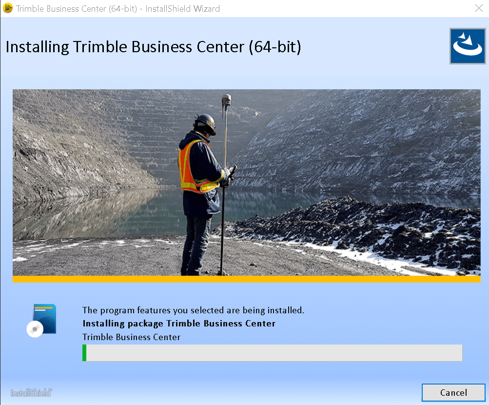
Here is a video of full installation of Trimble Business Center v5.50
All the new info about Trimble Business Center v5.50 all the release notes and improvements on install.
Recent Posts
🚀 Exciting Update: TBC 2023.11 Patch Release! 🚀We're thrilled to announce the latest patch for TBC, packed with crucial bug fixes and enhancements that promise to elevate your...
On October 21 2022 Trimble has released another release of its office software TBC version 5.80.It is available for users with the perpetual license users whose current warranty expiration date...